Craftsman 351.217570 Operator's Manual
Browse online or download Operator's Manual for Power tools Craftsman 351.217570. Craftsman 351.217570 Operator`s manual User Manual
- Page / 28
- Table of contents
- BOOKMARKS
- Operator's Manual 1
- © Sears, Roebuck and Co. 2 2
- ),, 30" 3
- Connected 5
- SPECIFICATIONS 6
- Moveworkevenly 8
- Motor will not start 10
- POSSIBLE CAUSE(S) 10
- Service Record 11
- Models 351.217570 12
- A Not shown 13
- 351.21 7570 16
- LIJADORA CON RECOLECTOR 16
- DE POLVO 16
- Modelo No 16
- _..,,_- 7'/s' -_ 17
- Perno (B) 18
- Tope horizontal 21
- Dust Shroud 22
- Tuercas de mariposa 23
- El motor no arranca 25
- Your Home 28
- Our Home 28
- 1-800-488-1222 28
Summary of Contents
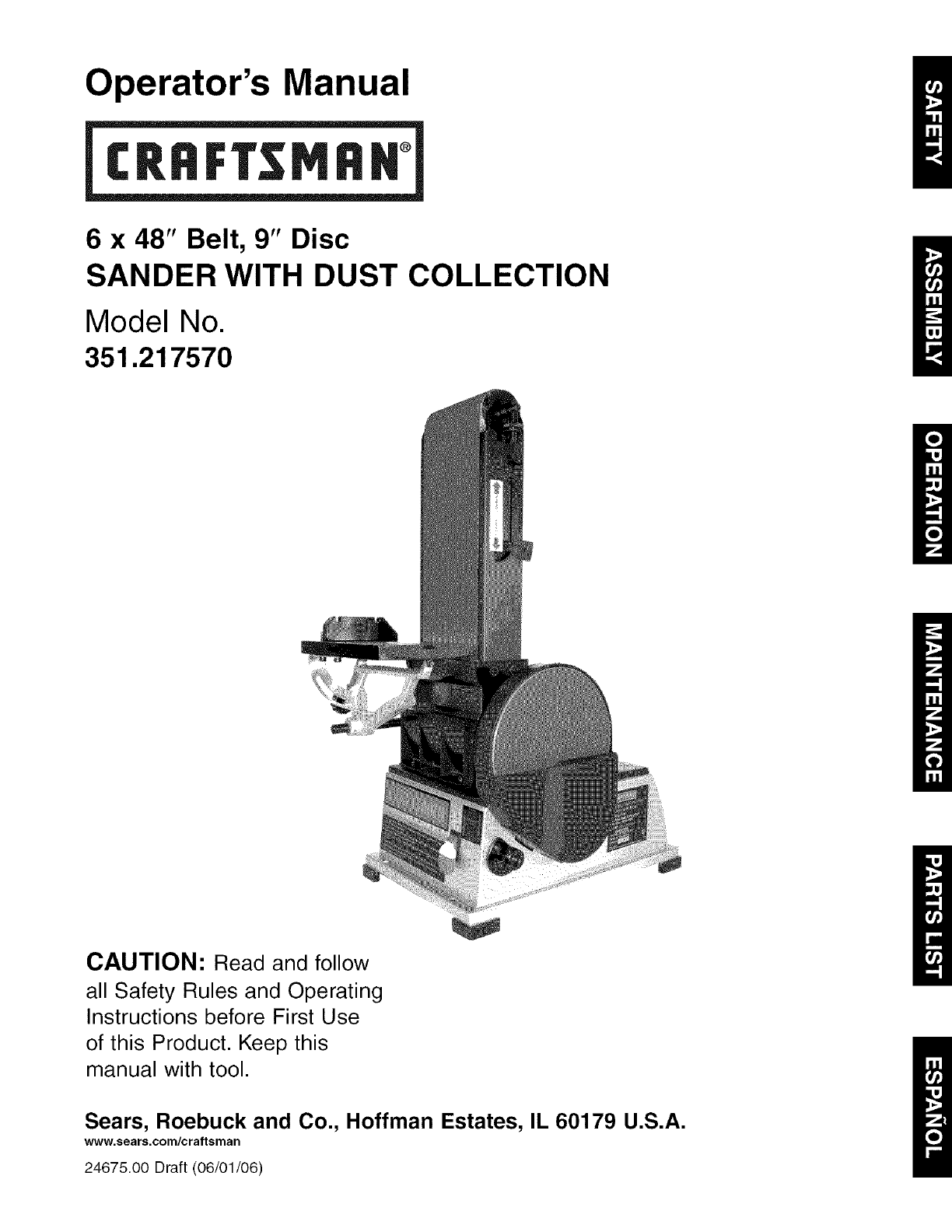
Operator's Manual6 x 48" Belt, 9" DiscSANDER WITH DUST COLLECTIONModel No.351.217570CAUTION: Read and followall Safety Rules and Operat
SYMPTOMMotor will not startMotor will not start;fuses blown or circuitbreakers are trippedPOSSIBLE CAUSE(S)1. Low voltage2. Open circuit in motor or l
Service RecordCraftsman Sander with Dust CollectionI DATE MAINTENANCE PERFORMED REPLACEMENT PARTS REQUIRED J11
Models 351.217570Figure 19 - Replacement Parts Illustration for Belt Housing6lO1123/# 2730 31 _3/36j_/826/1416 1712
KEYNO.12345678910111213141516171819202122232425262728293O3132333435363738394O41APART NO.21425.00STD840610STD84361021426.0024628.00STD83302521428.00207
Models 351.217570Figure 20 - Replacement Parts Illustration for Motor and Disc11241610411722133533214 41208 223131914
KEYNO.12345678910111213141516171819202122232425262728293O3132333435363738394O4142434445APART NO.STD87051007202.00STD870616STD851006STD86351024645.0024
LIJADORA CON RECOLECTORDE POLVOCorrea de 6 x 48" Disco de 9"Modelo No.351.21 7570PRECAUClON: Lea y siga todas las reglas deseguridad e inst
,, Evite que la herramienta se encienda accidentalmente.AsegL_rese que el interrupter de la herramienta esta en laposici6n OFF (apagado) antes de ench
INSTALACION DEL CONJUNTO DE LA MESAConsulte las Figuras 3 y 4.El conjunto de mesa incluido se utiliza con ambos, el disco yla correa.Para utilizar la
Consulte las Figuras 6, 7 y 8 en las paginas 19 y 20.FUENTE DE ALIMENTACIONADVERTENCIA: No conecte la lijadora a la fuente de alimenta-ci6n hasta habe
Warranty ... 2Safety Rules ... 2Unpacking ...
CONEXIONES ELECTRICASADVERTENCIA: Un electricista calificado debe hacer todaslas conexiones electricas. AsegQrese que la herramienta esteapagada y des
una mascara para la cara o respirador adecuadamente ajusta-dos, aprobados por OSHA/NIOSH.INTERRUPTOR DE ON/OFF (ENCENDIDO/APAGADO)Consulte la Figura 9
AJUSTE DEL ANGULO DE LA MESAConsulte la Figura 12.• Para ajustar el angulo de la mesa, afloje la manilla, inclinela mesa a la posici6n deseada, luego
Figura 14 - Verificaci6n del Paralelismo de la Ranura de laMesa a la Correa• Si es necesario ajustar la mesa, afloje los tres pernos queestgtn debajo
CAMBIO DEL DISCO ABRASlVOConsulte la Figura 18.,, Desmonte el conjunto de la mesa.,, Retire la cubierta del disco. Para esto, afloje y extraiga cincot
SINTOMAEl motor no arrancaEl motor no arranca; losfusibles estan quemadoso los cortacircuitos sehan disparadoEl motor no Iogradesarrollar toda supoten
NOTAS26
NOTAS27
Your HomeFor repair- in your home-of all major brand appliances,lawn and garden equipment, or heating and cooling systems,no matter who made it, no ma
Refer to Figure 1.Check for shipping damage. If damage has occurred, a claimmust be filled with carrier. Check for completeness.Immediately report mis
* Loosen knob. Using a combination square, set the tableperpendicular to the disc, and secure in position. Ifnecessary, set pointer at 0°.To use the t
WARNING: Do not permit fingers to touch the terminals ofplug when installing or removing from outlet.• Plug must be plugged into matching outlet that
SPECIFICATIONSMODEL 217570Belt size ... 6 x 48"Belt platen area ... 6 x 13W'Belt
\Tracking NutTension Lever/Figure 10 - Adjusting Belt TrackingADJUSTING BELT ASSEMBLY POSITIONRefer to Figure 11.Sanding belt assembly can be adjusted
* Finishinglongpieces:Usebeltinhorizontalpositionwithworkstop.Applyonlyenoughpressuretoallowabrasivebelttoremovematerial.Useworkstoptopositionandsecur
• Slide new belt over the drive and idler drums; center belton drums.• Additional abrasive belts are available (See RecommendedAccessories, page 15).•
Related products and manuals for Power tools Craftsman 351.217570
 (36 pages)
 (41 pages)
© 2020, manymanuals.com. All rights reserved. | 1.880 s |
 Manymanuals.com
 Manymanuals.de
 Manymanuals.fr
 Manymanuals.it
 Manymanuals.pl
 Manymanuals.cz
 Manymanuals.es
 Manymanuals-pt.com
Comments to this Manuals