Craftsman 316.74556 Operator's Manual
Browse online or download Operator's Manual for Garden tools Craftsman 316.74556. Craftsman 316.74556 Operator`s manual User Manual
- Page / 48
- Table of contents
- BOOKMARKS
- I:RI:IFI"$MI:IN 1
- THE ENGINE EXHAUST FROM THIS 2
- PRODUCT CONTAINS CHEMICALS 2
- OR OTHER REPRODUCTIVE HARM 2
- SAVE THESE INSTRUCTIONS 4
- 5"7x • PRIMER BULB 5
- Operator's Manual 7
- AttachmentShield 9
- RUN(IH C) 12
- CHECK FOR DAMAGED/WORN PARTS 14
- CLEAN UNIT AND LABELS 14
- 0.020 .mj" 15
- Idle Speed Screw 19
- /' (_ 24
- I:RI:IFTSMAN 26
- GUARDE ESTAS INSTRUCCIONES 29
- 5"7x 30
- Abrazadera Abrazadera 32
- Superior de Media de la 32
- (3.8 LITROS) (95 ml) 36
- (1',1s) 37
- RECOMENDACIONES GENERALES 39
- DESGASTADAS 39
- INSPECCIONE SI EXISTEN PARTES 39
- SUJETADORAS QUE ESTEN FLOJAS 39
- Perilla percusiva 41
- AJUSTEDELCARBURADOR 44
- PROBLEMA CAUSA SOLUCION 46
- H0meCentrals 48
Summary of Contents
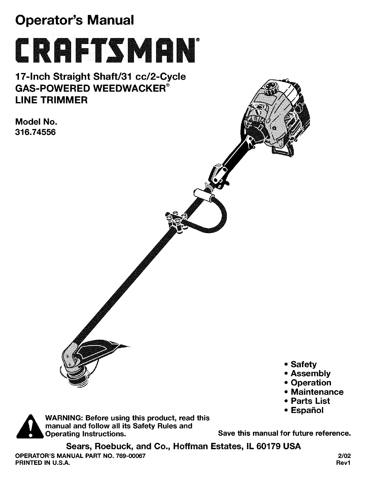
Operator's ManualI:RI:IFI"$MI:IN17-Inch Straight Shaft/31 cc/2-CycleGAS-POWERED WEEDWACKER ®LINE TRIMMERModel No.316.74556,_WARNING: Before
KNOW YOUR TRIMMERREAD THIS OPERATOR'S MANUAL AND SAFETYRULES BEFORE OPERATING YOUR UNIT. Compare theillustrations with your unit to familiarize y
THIS ENGINE IS CERTIFIED TO OPERATE ON UNLEADED GAS AND OIL MIXTURE,TO FUEL ENGINECAUTION: Be sure to read these instructionscarefully before attempti
IMPORTANTExperience indicates that alcohol blended fuels (calledgasohol or using ethanol or methanol) can attract moisturewhich leads to separation an
HOLDING THE TRIMMER,_ WARNING: Always wear eye, hearing, foot andbody protection to reduce the risk of injury whenoperating this unit.Before operating
MAINTENANCE SCHEDULEThese required maintenance procedures should beperformed at the frequency stated in the table. Theyshould also be included as part
Cleaning the Air FilterClean and re-oil the air filter every 10 hours of operation.It is an important item to maintain. Not maintaining theair filter
TO CLEAN UNITDo not use any strong detergents on the plastic housing orthe handle. They can be damaged by certain householdcleaners that contain aroma
4. Check the indexing teeth on the reel and reelhousing for wear. If necessary, remove any burrs orreplace the reel or reel housing (Fig. 22).Winding
SPARK ARRESTOR MAINTENANCE1. Remove air filter/muffler cover. See Removing theAir Filter/Muffler Cover.2.Locate muffler front and the two (2) bolts se
CARBURETOR ADJUSTMENTThe idle speed of the engine is adjustable through theAir filter/Muffler cover (Fig. 29).NOTE: Careless adjustments can seriously
Limited Warranty StatementCalifornia Proposition 65 WarningSpark ArrestorRules for Safe OperationContents of Hardware PackAssemblyOperation2 Maintenan
ENGINEEngine Type ... Air-Cooled, 2-CycleDisplacement ...
TROUBLE CAUSE REMEDYOn/Off Stop Control is "OFF" positionEmpty fuel tankPrimer bulb wasn't pushed enoughEngine will not startEngine wil
California / EPA Emission Control Warranty Statement;Your Warranty Rights and ObligationsThe California Air Resources Board, EPA (Environmental Protec
Item Part No. Description1 753-04114 Throttle Housing and TriggerAssembly (includes 2 & 3)2 792-610314 Throttle Trigger Spring3 753-04115 Throttle
//[@@@ @f/X'@@ @@' @ ,/' (_- 24 i
Item Part No. Description Item Part No. Description1 753-04105 Air Cleaner/Muffler Cover 33 791-181079 Pull HandleAssembly (includes 2 & 36) 34 79
Manual del OperadorI:RI:IFTSMANEje Recto de17 pulgadas/31 cc/2 ciclosRECORTADORA DE LINEAWEEDWACKER ®A GASOLINAModelo No.316.74556• Seguridad• Ensambl
Declaraci6n de Garantia Limitada E2Advertencia de la Proposici6n 65 de California E2Parachispas E2Normas para una operaci6n segura E3Contenidos de la
Los slmbolos de seguddad se utilizan para Ilamar suatenci6n sobre posibles peligros. Los slmbolos deseguridad y sus explicaciones merecen toda su aten
• La protecci6n accesoria de corte debe estar siemprecolocada 8n su lugar m_en_rasopere la unidad. No opere launidad con las dos lineas de corte exten
The purpose of safety symbols is to attract yourattention to possible dangers. The safety symbols, andtheir explanations, deserve your careful attenti
SIMBOLOS DE SEGURIDAD E INTERNACIONALESEste manual del operador describe los simbolos y figuras de seguridad e intemacionales que pueden aparecer en e
SiMBOLO SIGNIFICADO• INDICADOR DE ACEITEConsulte el manual del operador para obtener informaciSn acerca del tipo correcto de aceite./ /• LOS OBJETOS D
Manual delOperadorProtecci6n deLinea de 17"(3) Tomillos (10-24 x 1/2) - parala Protecci6n de la LineaAbrazadera AbrazaderaSuperior de Media de la
CONTENIDO DE LA CAJA• Recortadora• Paquete de PiezasHERRAMIENTAS NECESARIAS PARA ELENSAMBLE• Destornillador Phillips GrandeINFORMACI(_N ACERCA DEL ENS
INSTALACI6N DEL PROTECTOR ACCESORIO Protector accesorioDE CORTE de corte de 17"Siga las siguientes instrucciones si el protector accesoriode cort
CONOZCA SU RECORTADOR DE LiNEALEA ESTE MANUAL DEL OPERADOR Y LAS NORMAS DESEGURIDAD ANTES DE OPERAR SU RECORTADORA DELINEA. Compare las figuras con su
ESTE MOTOR ESTA CERTIFICADO PARA OPERAR CON UNA MEZCLA DEGASOLINA SIN PLOMO Y ACEITE.PARA ALIMENTAR EL MOTORPRECAUCION: Asegt_rese de leer estasinstru
IMPORTANTELa experiencia indica que los combustibles con mezcla dealcohol (llamados gasohol o que usan etanol o metanol)pueden atraer humedad Io coal
C6MO SOSTENER EL RECORTADOR,_ ADVERTENCIA: Use siempre protecci6n parasus ojos, audici6n, pies y cuerpo para reducirel riesgo de una lesi6n al operar
NOTA: AIgunos procedimientos de mantenimiento puedenrequedr el uso de herramientas o habilidadesespeciales. Si no est& seguro acerca de estosproce
• Be sure the cutting attachment is not in contact withanything 3efore starting the unit.• The cutting attachment shield must always be in placewhile
2,3.Saaue los cuatro (4) tornillos aue sostienen la cubierta de]filtro de aire / silenciador (Fig. 13L Use un destornillaaorde v&stago piano o un
LIMPIEZA DE LA RECORTADORA DE LJNEANo use detergentes fuertes para limpiar el bastidor depl&stico ni la manija. Estas piezas pueden da_arse ya que
Bobinado del Carrete1. Tome aproximadamente 25 pies (7.6 m) de linea decorte nueva. Enl&cela en dos largos iguales. Insertecada extremo de la line
MANTENIMIENTO DEL PARACHISPASNota: El flujo de las emisiones puecle ser en unadireccion solamente: APARTANDOSE del motor.Preste mucha atenci6n a c6mo
AJUSTEDELCARBURADORLa velocidad lenta del motor puede set ajustada per la cubiertadel silenciador/filtro de aire (Fig. 28}.NOTA: LOSajustes realizados
MOTORTipo de motor ... Enfriado por aire, de 2 ciclosDesplazamiento ...
PROBLEMA CAUSA SOLUCIONEl motor no arrancaEl motor no funciona en minimaEl motor no aceleraEl motor no tiene potencia ose para al cortarEl accesorio d
DECLARACION DE LA GARANTIA DE CONTROLDE EMISIONES DE CALIFORNIA / EPA;SUS DERECHOS DE GARANT|A Y OBLIGACIONESLa Junta de Recursos dal Aire de Californ
For in-home major brand repair service:Call 24 hours a day, 7 days a week1-800-4-MY-HOME s" (1-800-469-4663)Para pedir servicio de reparacibn a d
SAFETY AND INTERNATIONAL SYMBOLSThis operator's manual describes safety and international symbols and pictographs that may appear on this product
SYMBOL MEANING• OILRefer to operator's manual for the proper type of oil.• THROWN OBJECTS AND ROTATING CUTTER CAN CAUSE SEVERE INJURYWARNING: Do
Operator's Manual17" CuttingAttachment Shield(3) Screws (10-24 x 1/2) - forCutting Attachment ShieldTop Clamp Middle ClampBottle of Oil(3) H
CARTON CONTENTS• Trimmer• Hardware PackTOOLS REQUIRED FOR ASSEMBLY• Large Phillips ScrewdriverASSEMBLY INFORMATIONTo ensure safe and proper operation
INSTALLINGTHECUTTINGATTACHMENTSHIELD CuttingAttachmentShieldUse the following instructions if the cutting attachmentshield on your unit is not install
Related products and manuals for Garden tools Craftsman 316.74556
 (44 pages)
 (16 pages)
(12 pages)
(12 pages)
(16 pages)
(16 pages)
(12 pages)
(12 pages)
© 2020, manymanuals.com. All rights reserved. | 2.103 s |
 Manymanuals.com
 Manymanuals.de
 Manymanuals.fr
 Manymanuals.it
 Manymanuals.pl
 Manymanuals.cz
 Manymanuals.es
 Manymanuals-pt.com
Comments to this Manuals