Craftsman 139.53644SRT Operations Instructions
Browse online or download Operations Instructions for Garage Door Opener Craftsman 139.53644SRT. Craftsman 139.53644SRT Operating instructions User Manual
- Page / 40
- Table of contents
- BOOKMARKS
- I:RRFTSMRNo 1
- Mechanical Electrical 2
- You'll Need Tools 3
- HeaderCorved I 5
- Carton inventory 6
- _ IIllllllllllllllllll]> 7
- Assembly Step 1 8
- Assembly Step 2 9
- Assembly Step 3 I 9
- Assembly Step 4 10
- Assembly Step 5 11
- Pages 12- 27 12
- Proceed to Step 2, page 14 13
- Vertical 14
- Position the Opener 16
- Figure 2 17
- Hang the Opener 17
- Figure 1 17
- Installation Step 7 I 19
- Installation Step 8 19
- Electrical Requirements 20
- Permanent 20
- Connections 20
- The Safety Reversing System 21
- Figure 3 22
- Figure 4 22
- Figure 5 22
- Figure 6 23
- Fasten Door Bracket 24
- Figure I 24
- _0 Door I_ Straight 26
- AssembletheDoorArm: 27
- Adjustment Step 1 28
- Adjustment Step 2 I 29
- Adjustment Step 3 30
- Adjustment Step 4 30
- 8.SAVE THESE iNSTRUCTiONS 31
- Care of Your Opener 31
- Operation of Your Opener 32
- (With "SRT" Button) 33
- Having a Problem? 34
- Having a Problem? (continued) 35
- Repair Parts 36
- 139.53709 38
- CRAFTSMAN° 40
Summary of Contents
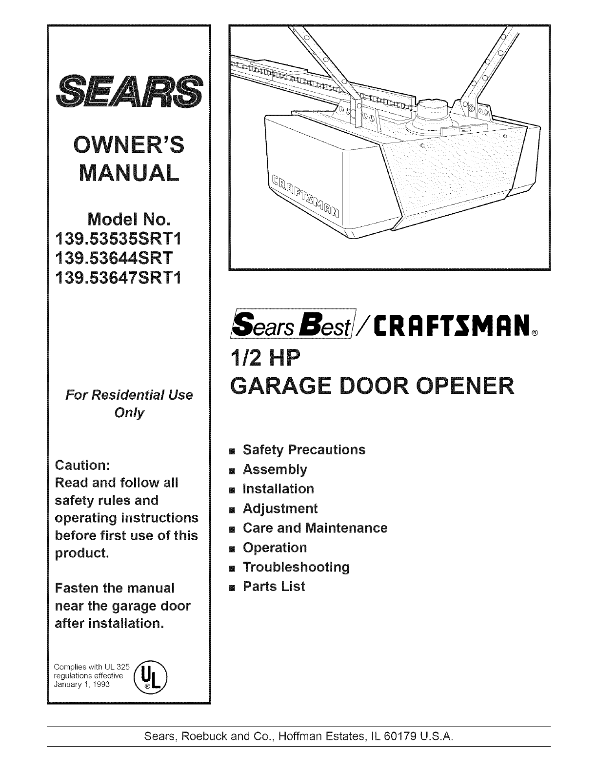
OWNER'SUALModel No.139.53535SRT1139.53644SRT139.53647SRT1For Residential UseOnlyCaution:Read and follow allsafety rules andoperating instructions
Assembly Step 4Install the Chain/Cable &Attach the Sprocket CoverDispensing CartonLeave Chain and CableInside DispensingCarton to Prevent Kinking.
Assembly Step 5Tighten the Chain & Cable• Spin the inner nut and lock washer down thethreaded shaft, away from the trolley.• To tighten the chain,
installation Section:installation Step 1Determine Header Bracket LocationInstallation procedures vary according togarage door types. Follow the instru
Read the Safety instructions on page 12. They also apply to doors without tracks.* Close the door and mark theinside vertical centerline ofyour garage
Youcanattach the header bracket either to thewall above the garage door, or to the ceiling,Follow the instructions which will work best foryour partic
installation Step 3Attach the T=rai! to the Header Bracket--Header WallHeaderBracketCablePulleyBracket• Position the opener on the garage floor below
installation Step 4Position the OpenerFollow instructions which apply to your doortype as illustrated.A 2×4 laid fiat is convenient for setting an ide
installation Step 5Hang the OpenerTwo representative installations are shown.Yours may be different. Hanging brackets shouldbe angled, Figure 1, to pr
installation Step 6Install the Premium Control ConsoleLocate the door control within sight of the doorat a minimum height of 5 feet where smallchildre
6.AttachtheUserSafetyInstructionlabeltothewallnearthedoorcontrol,andtheMaintenanceInstructionlabelina prominentlocationontheinsideof thegaragedoor.Pag
Contents PageA review of safety alert symbols ... 2You'll need tools ...
installation Step 9Electrical RequirementsTo reduce the risk of electric shock, your garagedoor opener has a grounding type plug with a thirdgrounding
The Safety Reversing SystemInformation you'll need before you begin the installation of the safety reversing sensor.The safety reversing sensor m
installation Step 10 Iinstall the Safety Reversing SensorFigures 2 and 3 show assembly of brackets and"C" wrap based on the recommended inst
* Center each sensor unit in a "C" wrap with lensespointing toward each other across the door (seeFigure 6).Secure sensors with the hardware
installation Step 11Fasten Door BracketFollow instructions which apply to your doortype as illustrated below or on page 25.To prevent damage to steel,
Please read and comply with the warnings and reinforcement instructions on page 24.They apply to one-piece doors also.Header Walt-- Finished Ceiling -
installation Step 12Connect Door Arm to TrolleyFollow instructions which apply to your doortype as illustrated below and on page 27.Make sure garage d
AssembletheDoorArm:• Fastenthestraightandcurveddoorarmsectionstogethertothelongest possible length, with a 2 or 3hole overlap.• With the door closed,
Adjustment Section: Pages 28 - 30Adjustment Step 1Adjust the UP and DOWN LimitsDo not make any limit adjustments until thesafety reversing sensors are
Adjustment Step 2 IAdjust the ForceForce adjustment controls are located on the rightside panel of the opener. Force adjustment settingsregulate the a
You'll Need ToolsDuring assembly, installation and adjustment of the opener, instructions will call for hand tools shown below.Carpenter'sLe
Adjustment Step 3Test The Safety Reversing Sensor• Press the remote control push button to open thedoor.• Place the opener carton in the path of the d
iMPORTANT SAFETY iNSTRUCTiONSTo reduce the risk of severe injury or death to persons:1. READ AND FOLLOW ALL iNSTRUCTiONS.2. Do not permit children eit
Operation of Your OpenerActivate the opener with any of the following:• The Remote Control: Hold push button downuntil the door starts to move.• The D
Receiver and Remote Control ProgrammingTo comply with FCC rules, adjustment or modifications of this receiverand/or transmitter are prohibited, except
Having a Problem?Situation Probable Cause and SolutionThe opener doesn't 1. Does the opener have electric power? Plug a lamp into the outlet. If
Having a Problem? (continued)Situation Probable Cause & SolutionThe door opens but 1. If the opener lights blink, check the safety reversing senso
Repair PartsRail Assembly__Parts _ J_i 3 J 475 4 1 1A995 Master link kit2 41A3489 Complete trolley assembly3 1B3117 T-rail - center section4 183Bl10 T
Repair PartsOpener Assembly PaNsI2O19 18I5 17 __16151314I7D 8i i,,_(Down) LIMIT SWITCHBrown Contact ASSEMBLYWire _/'1_Drive_Gear , _Center Lirnit
AccessoriesSears offers many useful accessories for your garage door opener. They are illustrated below withSears model numbers and descriptions.139.5
indexAccess Door/Outside Key Release Accessory ... 4, 5Cha
Before you begin, survey your garage area tosee whether any of the conditions below applyto your installation.Horizontal and vertical reinforcementis
OWNER'SMANUALModel No.139.53535SRTI139.53644SRT139.53647SRTIThe model numberlabel is located underthe light lens on theleft side panel of yourope
One-Piece Door without TrackBefore you begin, survey your garage area tosee whether any of the conditions below applyto your installation.Slack in cha
Carton inventoryYour garage door opener is packaged in two cartons which contain all parts illustrated below. If anything ismissing, carefully check t
Separate all hardware from the packages in the rail carton and the opener carton, asshown below, for the assembly and installation procedures.Assembly
Assembly Section: Pages 8 - 11To avoid installation difficulties, do not run the garage door opener until instructed to do so.Assembly Step 1Assemble
Assembly Step 2install the Trolley on the T-rail* Attach the threaded shaft to the trolley with thelock washer and nuts as shown.TrolleyOuter NutLock
Related products and manuals for Garage Door Opener Craftsman 139.53644SRT

 (66 pages)
 (80 pages)
© 2020, manymanuals.com. All rights reserved. | 1.021 s |
 Manymanuals.com
 Manymanuals.de
 Manymanuals.fr
 Manymanuals.it
 Manymanuals.pl
 Manymanuals.cz
 Manymanuals.es
 Manymanuals-pt.com
Comments to this Manuals