Craftsman 139.53910 User Manual
Browse online or download User Manual for Equipment Craftsman 139.53910. Craftsman 139.53910 User Manual
- Page / 76
- Table of contents
- BOOKMARKS
- GARAGE DOOR OPENER 1
- ABRIDOR DE PUERTA DE COCHERA 1
- Preparing your garage door 3
- Toots needed 3
- Planning 4
- Carton Inventory 6
- Hardware Inventory 7
- Assemb/e the 8
- ASSEMBLY STEP 1 8
- ASSEMBLY STEP 3 9
- ASSEMBLY STEP 4 10
- INSTALLATION 11
- £k WARNING 12
- INSTALLATION STEP 2 13
- INSTALLATION STEP 3 14
- INSTALLATION STEP 4 15
- A WARNING 16
- INSTALLATION STEP 6 17
- WARNING 20
- Indicator 21
- Light Sensor 21
- INSTALLATION STEP 11 23
- INSTALLATION STEP 12 25
- IMPORTANT SAFETY INSTRUCTIONS 30
- 15 SAVE THESE INSTRUCTIONS 30
- Using the Wall-Mounted 31
- Door Control 31
- To Open the Door Manually 31
- Á WARNING 32
- HAVIIUG A PROBLEM? 33
- Diagnostic Chart 34
- To Erase All Codes From Motor 35
- REPAIR PARTS 37
- DAPT ' DAPT 38
- ACCESSORIES 39
- WARRANTY 39
- ADVERTENCIA 40
- PRECAUCIÓN 40
- PRECAUCION 41
- Planificación 42
- 0'.£ 45
- ^asEdo'Cschasfste 45
- LA INSTALACIÓN 49
- A ADVERTENCIA 49
- INSTALACION, PASO 2 51
- INSTALACION, PASO 3 52
- INSTALACION DE LAS MENSULAS 59
- Pe-no da cscns — 60
- PUERTAS DE UNA SOLA PIEZA 62
- INSTALACION, PASO 12 63
- se Indica 64
- SI TIENE ALGUN PROBLEMA 71
- Tabla de Diagnóstico 72
- COMO PROGRAMAR EL ABRIDOR 73
- Entrada 74
- ACCESORIOS 75
- GARANTIA 75
- (1-800-533-6937) 76
Summary of Contents
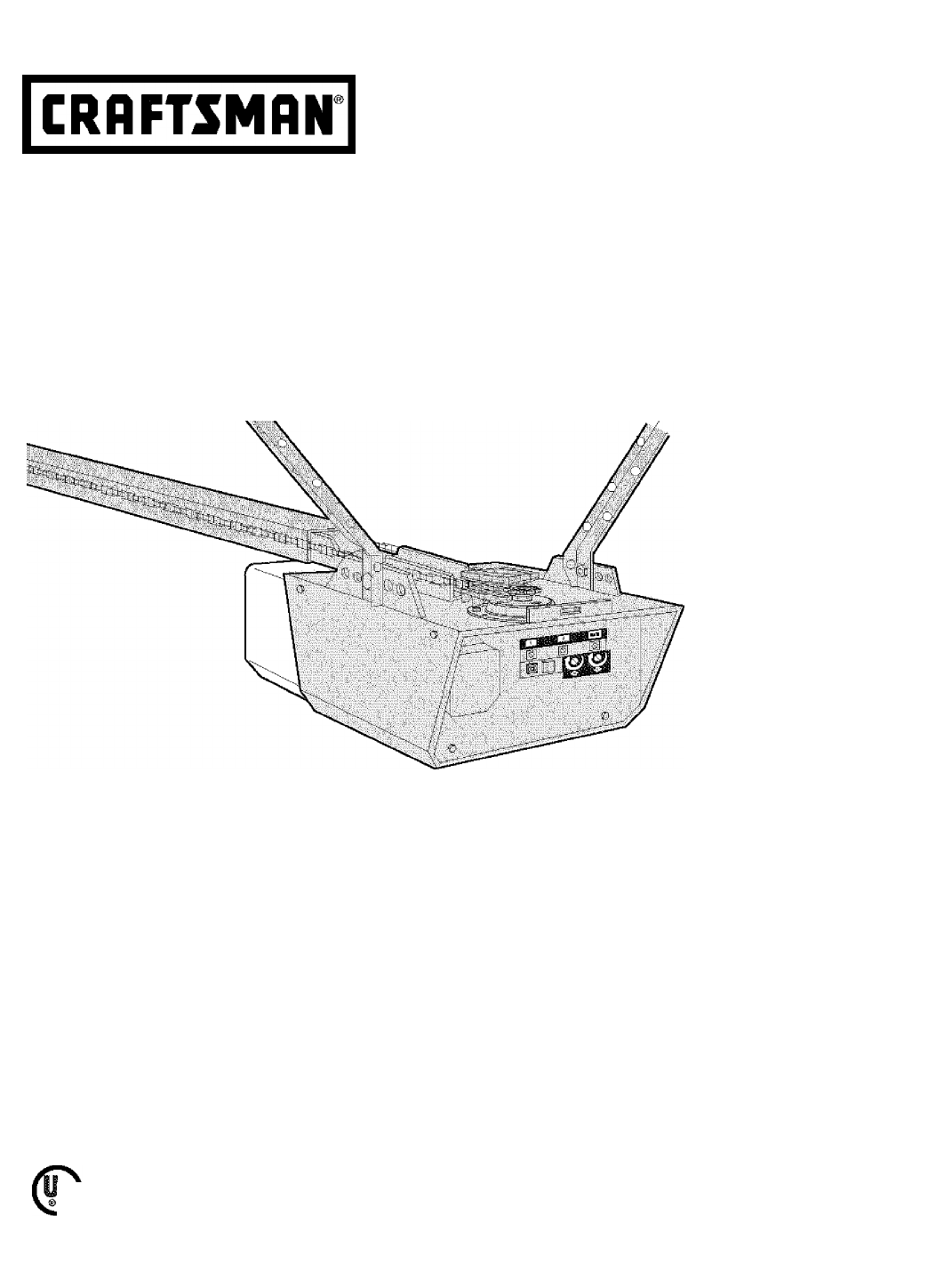
Owner’s Manual/Manual Del Propietario1/2 HPGARAGE DOOR OPENER ABRIDOR DE PUERTA DE COCHERAFor Residential Use Oniy/Sólo para uso residencial Model/Mod
Install the Chain/Cable1. Pull the cable around the idler pulley and toward the trolley.2. Connect the cable to the retaining slot on the trolley, as
Tighten the Chain• Spin the inner nut and lock washer down the trolley threaded shaft, away from the trolley.• To tighten the chain, turn outer nut
Determine the Header Bracket LocationINSTALLATION STEP 1Unfinished Ceiling£k WARNINGTo prevent possible SERIOUS INJURY or DEATH:• Header bracket MUST
Install the Header BracketYou can attach the header bracket either to the wall above the garage door, or to the ceiling. Follow the instructions which
-Headar Wall- Header Bracket idler PulleyAttach the Rail to the Header BracketNOTE: (Optional) With some existing installations, you may re-use the ol
INSTALLATION STEP 4Position the OpenerFollow instructions which apply to your door type asillustrated.SECTIONAL DOOR OR ONE-PIECE DOOR WITHTRACKA 2x4
Hang the OpenerThree representative instailations are shown. Yours may be different. Hanging brackets shouid be angled (Figure 1) to provide rigid sup
INSTALLATION STEP 6Install the Door ControlLocate door control within sight of door, at a minimum height of 5 feet (1.52 m) where small children canno
Install the Light• Install a 75 watt maximum light bulb in the socket. The light will turn ON and remain lit for approximately 4-1/2 minutes when pow
Electrical RequirementsTo avoid installation difficulties, do not run the opener at this time.To reduce the risk of electric shock, your garage door o
TABLE OF CONTENTSIntroduction 2-7Safety symbol and signal word review...2Preparing your garage door...
Install The Protector System^The safety reversing sensor must be connected and aligned correctly before the garage door opener will move in the down d
Be sure power to the opener is disconnected.Install and align the brackets so the sensors wif! face each other across the garage door, with the beam n
MOUNTING AND WIRING THE SAFETY SENSORS• Slide a 1/4"-20x1/2" carriage bolt head into the slot on each sensor. Use wing nuts to fasten senso
Fasten the Door BracketFoüow instructions which apply to your door type as illustrated below or on the following page.A horizontal reinforcement brace
ONE-PIECE DOORSPlease read and comply with the warnings and reinforcement instructions on the previous page. They apply to one-piece doors also.• Cen
Connect Door Arm to TrolleyFoiiow instructions which apply to your door type asiHustrated below and on the following page.SECTIONAL DOORS ONLY• Make
ALL ONE-PIECE DOORS1. Assemble the door arm, Figure 4:• Fasten the straight and curved door arm sections together to the longest possible length {with
ADJUSTMENT STEP 1Adjust the UP and DOWN Travel LimitsLimit adjustment settings regulate the points at which the door wiil stop when moving up or down.
ADJUSTMENT STEP 2Adjust the ForceForce adjustment controls are located on the back panel of the motor unit. Force adjustment settings regulate the amo
ADJUSTMENT STEP 3Test the Safety Reversal SystemTEST• With the door fully open, place a 1-1/2" (3.8 cm) board (or a 2x4 laid flat) on the floor,
Preparing your garage doorBefore you begin:• Disable locks.• Remove any ropes connected to garage door.• Complete the following test to make sure y
OPERATIONIMPORTANT SAFETY INSTRUCTIONS.. .. .. .. .. .. .. .. .. .. .. .. .. .. .. .. .. .. .. .. .. .. .. .. .. .. .. .. .. .. .. .. .. .. .. .. .. .
Using the Wall-Mounted Door Control ^Press the lighted push button to open or close the door. Press again to reverse the door during the closing cy
CARE OF YOUR OPENERLIMIT AND FORCE ADJUSTMENTS:Weather conditions may cause some minor changes in door operation requiring some re-adjustments, partic
HAVIIUG A PROBLEM?1.My door will not close and the light bulbs blink on my motor unit: The safety reversing sensor must be connected and aligned corre
Safety SensorDiagnostic ChartYour garage door opener is programmed with self-diagnostic capabiiities. The “Learn” buttonidiagnostic LED will flash a n
programmingNOTICE: If this Securityi^garage door opener is operated with a non-roiling code transmitter, the technical measure in the receiver of the
To Addf Reprogram or Change a Keyless Entry PINNOTE: Your new Keyless Entry must be programmed to operate your garage door opener.USING THE “LEARN” BU
REPAIR PARTSNO...NO...DESCRIPTION ...1 ; 4A1008 .Master link kit2...V41C5141-1.^.Complete trolley assembly3. : 41A5665. .. Co
Motar Unit Assembly P&rtsCere' i" Í :Cp)CoTj.-; Cci-jSiiiTPV DAPT ' DAPTNO. NO.DESCRIPTIONNO. NO. iDEiCRIiPTION141A5ei541C4220ACh
ACCESSORIES139.53702еЛ^firn139.5372641A52S1139.53 09Emercjency Key Release:Requ red fo‘ a garage w th \0 access doo'. Erabes loneowrer :o ooen ga
Planningidentify the type and height of your garage door. Survey your garage area to see if any of the conditions beiow apply to your installation. Ad
CONTENIDOintroducción 2-7Revisión de los símbolos y términos de seguridad...2Preparación de la puerta de su cochera...3Herramient
Preparación efe la puerta efe su cocheraAntes de comenzar:” Quite los seguros.“ Retire cualquier cuerda o cable que esté conectado a la puerta.• Haga
PlanificaciónIdentifique ia aitura y ei tipo de su puerta de cochera. Revise el área de su cochera y observe si alguna de las siguientes instalaciones
Planificación (continúa)INSTALACIÓN CON PUERTAS DE UNA SOLA PIEZA“ Generalmente una puerta de una sola pieza no requiere refuerzos adicionales. Si ust
inventarío efe la Caja efe CartónSu abridor viene empacado en una ca|a de cartón que contiene el motor y las piezas que se muestran en la siguiente il
Inventarío de PiezasArtes de la instalación, organice todas las piezas en grupos como se muestra en la siguiente ilustración.=strs ce coche ce -'
Monte el Riel e instale el TroleNo encienda ni use el abridor hasta que llegue al paso de la instalación correspondiente, de otra manera corre el ries
Fije el Riel a la Unidad del Motor" Coloque un perno de 1/4-20x1 -3/4 de pulg. dentro del ortíicio de la cubierta de protección que se encuentra
ínstale la Cadena y Cable1. Jale el cable alrededor de la polea loca y hacia el trole.2. Conecte la cable a la ranura de retención del trole, oomo se
Aprfefe la Cadena" Gire la tuerca interna y ajuste la arandela; baje ambas por el eje roscado del trole, alejándolas del trole.“ Para apretar la
Planning (Continued)ONE-PIECE DOOR INSTALLATIONS• Generally, a one-piece door does not require reinforcement. If your door is lightweight, refer to t
Detetmine cfónde va a instalar la Alénsiffa d&t Csá>&zatINSTALACION, PASO 1ADVERTENCIAPara evitar una posible LESIÓN GRAVE o INCLUSO LA
instale la Ménsula cfef CabezalLa ménsula del cabezal se puede fijar a la pared justo por encima de la puerta de la cochera o en el cielo raso. Siga l
Coloifue el Riel en la Ménsula del CabezalINSTALACION, PASO 3Pa”®cl dslaniera ... - Ménsula sal caoeial - Polsa locaMénsulacolcstsaaO'lao ds mo
INSTALACION, PASO 4Coloque el Abrítíor en PosiciónSiga las instrucciones correspondientes al tipo de puerta de su cochera, como se muestra en la ilust
Cuelgue el AímúetAquí se muestran tres e|emplos distintos para la tnstalación; sin embargo, es posible que su cochera no concuerda con ninguno de ello
Instale la Unidad de ConUol de la PuertaUbique 8l control de la puerta de manera que quede a la vista desde la puerta y a una altura mínima de 1.52 m
Instate la Luce- Oprima las lengüetas de liberación a ambos lados de la lente. Rote la lente suavemente hada atrás y hada abajo hasta que la bisagra q
Requisitos para ia Instaíaeión EléctricaPara evtter dificultades con la Instalación, no encienda ni use el abridor en este momento.Para reducir el rie
¡nstale La Sistema de Protecciórí^El sensor del sistema de retroceso de seguridad debe estar Instalado y alineado correctamente, antes de que el abrid
Asegúrese de que el abridor no esté conectado a lacorriente eléctrica.Instale y alinee las ménsulas de manera que los sensores estén uno frente al otr
Carton InventoryYour garage door opener is packaged in one carton which contains the motor unit and aii parts iliustrated below. Accessories will depe
MONTAJE Y CABLEADO DE LOS SENSORES DEL SISTEI^A DE RETROCESO DE SEGURIDAD” Deslice la cabeza de un perno de coche de 1/4-20x1/2 de pulgada dentro de
INSTALACION, PASO 11Fije la Ménsula de la PuertaSiga las tnstrucdones que correspondan al tipo de puerta de cochera que usted tenga, como se muestra e
Lea y respete todas las advertencias e instruociones respecto a los refuerzos, contenidas en la página anterior, instalación de puertas seccionales, y
Conecte el Brazo efe la Puerta al TroleSiga las instrucciones que correspondan al tipo do puertade iXíchera que usted tenga, txsmo se muestraa continu
1. Arme el b¡^o de Is puerts, Flgum 4:- Sujete las dos secciones de los brazos de la puerta (recto y curvo) a la mayor distancia posible, de manera q
AJUSTES, PASO 1Ajuste el Límite del Recorrido HACIA ARRIBA y HACIA ABAJOAl ajustar el límite del recorrido de la puerta, se regula hasta qué punto ést
AJUSTES, PASO 2Ajuste la FuerzaLos controles para el ajuste de la fuerza del abridor se encuentran en el panel de posterior de la unidad del motor. Es
AJUSTES, PASO 3P№el»e el Sistema de Retroceso de SeguridadPRUEBA” Abra completamente la puerta, coloque un pedazo de madera de 3.8 cm (1-1/2 pulg.) (o
OPERACIONINSTRUCCIONES IMPORTANTES DE SEGURIDADA ADVERTENCIAPara reducir el riesgo de lesiones graves o la muerte:1. LEA Y SIGA TODAS LAS ADVERTENCIAS
Cónw Usar ia Unidad da Control de ParedOprima el botón iluminado para abrir o cerrar la puerta. Oprima de nuevo para que la puerta retroceda en el dol
Separate all hardware and group as shown below for the assembly and installation procedures.Hardware Inventory
MANTENIMIENTO DE SU ABRIDOR DE PUERTA DE COCHERALA BATERIA DEL CONTROL RECIOTOCONTROLES DE FUERZACONTROLES DE LIIVIfTEOAJUSTES DE LIMITE Y FUERZA
SI TIENE ALGUN PROBLEMA. La puerta no cierra y las luces de la unidad del motor parpadean: El sensor del sistema de retroceso de seguridad debe estar
Tabla de DiagnósticoEl circuito de ios sensores de seguridad está abierto (cable roto o desconectado).O BIENBZBHay un cortocircuito en ei cable de los
COMO PROGRAMAR EL ABRIDORAVISO: Si utiliza este abre pueitas de garaje Seouriiy*^ oon un transmisor no dotado de un sistema de códigos de salto (códig
Cómo Agregatj Reprogramae o Cambiar un Código de Entrada sin LlaveNOTA: Su nueva Entrada sin Have debe programarse para que opere el abridor de la pue
ACCESORIOS139.53702139.53726139.5^8941A5281Extensión del riel de 3 m (10 pies):Permite que una puerta de 3 m (10 pies) se abra completamente.Liberador
Get it fixed, at your home or ours!Your HomeFor repair-in your home-of all major brand appliances, lawn and garden equipment, or heating and cooling s
Assemb/e the Rail & Install the TielleyTo avoid installation difficulties, do not run the garage door opener until instructed to do so.The front r
assembly step 2Fasten the Rail to the Motor Unit• Insert a 1/4’'-20x 1-3/4 bolt into the cover protection bolt hole on the back end of the rail
Related products and manuals for Equipment Craftsman 139.53910

 (60 pages)
(30 pages)
(30 pages)
(22 pages)
(28 pages)
(28 pages)
(40 pages)
(20 pages)
(16 pages)
(25 pages)
(36 pages)
(12 pages)
(82 pages)
(44 pages)
(20 pages)
(60 pages)
(30 pages)
(30 pages)
(22 pages)
(28 pages)
(28 pages)
(40 pages)
(20 pages)
(16 pages)
(25 pages)
(36 pages)
(12 pages)
(82 pages)
(44 pages)
(20 pages)
© 2020, manymanuals.com. All rights reserved. | 0.120 s |
 Manymanuals.com
 Manymanuals.de
 Manymanuals.fr
 Manymanuals.it
 Manymanuals.pl
 Manymanuals.cz
 Manymanuals.es
 Manymanuals-pt.com
Comments to this Manuals