Craftsman 247.886640 Owner's Manual
Browse online or download Owner's Manual for Snow throwers Craftsman 247.886640. Craftsman 247.886640 Owner`s manual User Manual
- Page / 33
- Table of contents
- BOOKMARKS
- Owner's Manual 1
- Snow Thrower 1
- Training 3
- Preparation 3
- Operation 3
- Maintenance and Storage 4
- (7,,-'0'7%__") 5
- • S_own on page 5 6
- (Usehardware group A.) 7
- Attaching Shift Lever 7
- Attaching Control Cables 7
- Attaching Chute Assembly 8
- Knowing your Snow Thrower 10
- Operating Controls 10
- Stopping the engine 10
- Before Starting 11
- Before Starting Engine 11
- To Start Engine 11
- To Engage Drive 12
- To Stop Engine 12
- Check; service ifneeded 13
- Tire Pressure 15
- Making Adjustments 15
- Servicing Augers 16
- Shave Plate and Skid Shoes 16
- Replacing Belts 17
- Friction Wheel 18
- Plates '_ 18
- Figure 28 18
- Preparing Engine 19
- Preparing Snow Thrower 19
- _ FRAM ER_j_'_DEPERiF 21
- 41 5 Auger Clutch 28
- 287 390 3/70K 30
- Table continued on next page 31
Summary of Contents
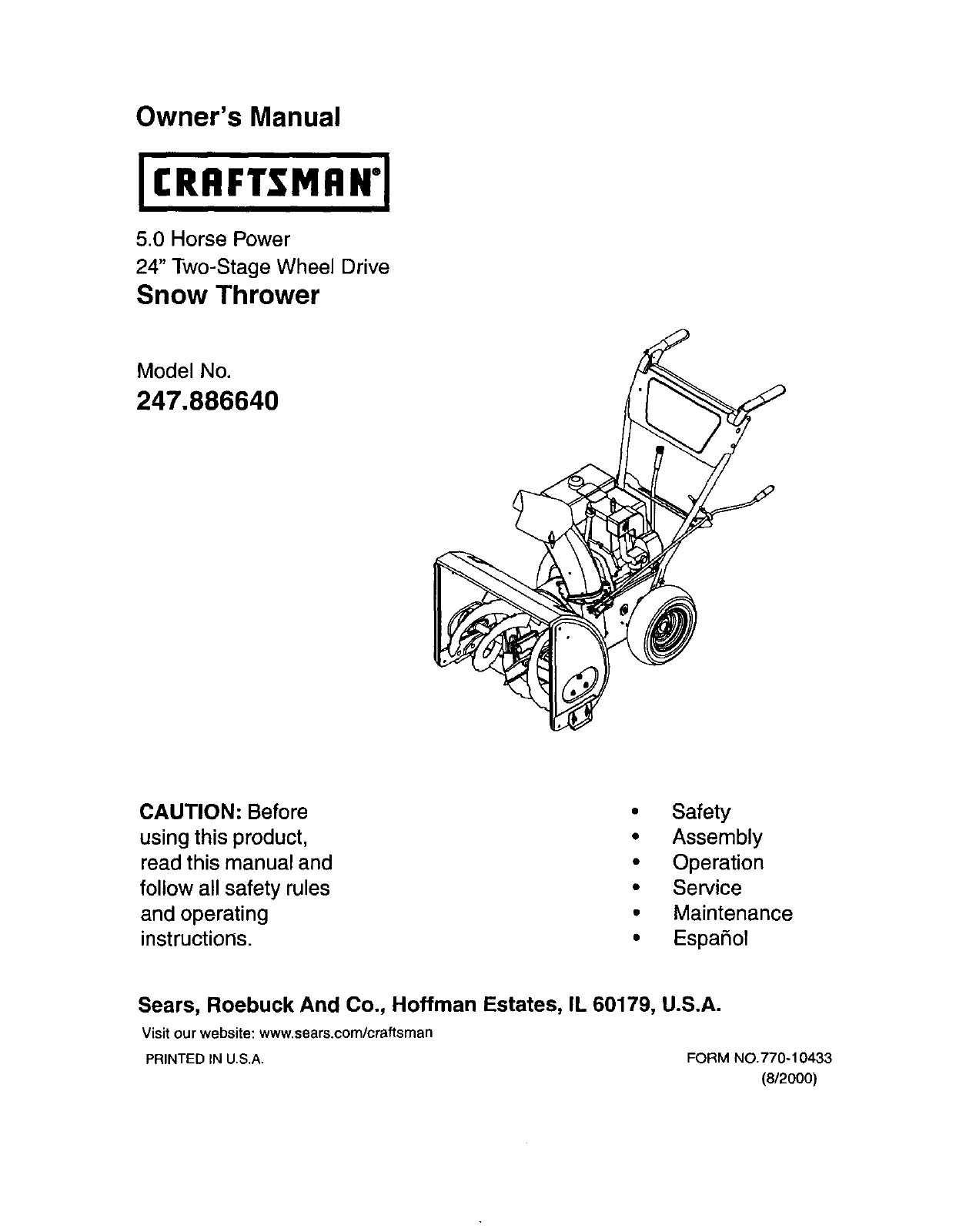
Owner's Manual5.0 Horse Power24" Two-Stage Wheel DriveSnow ThrowerModel No.247.886640CAUTION: Beforeusing this product,read this manual andf
Knowing your Snow Thrower,_ WARNING: Be familiar with all the controlsand their proper operation. Know how to stop the machineand disengage them quick
Before StartingWARNING: Read, understand, and followall instructions and warnings on the machineand in this manual before operating.• The engine was s
When engine starts, release starter button, andmove choke gradually to OFF. If engine falters,move choke immediately to FULL and thengradually to OFF.
To Engage Augers• To engage the augers and start throwingsnow,squeeze the auger controlgrip against the lefthandle. Release to stopthe augers.Operatin
Lubrication&WARNING: Before lubricating, repairing, orinspecting, disengage all clutch levers andstop engine. Wait until all moving parts havecome
NOTE: Althoughmulti-viscosity oils (5W30, 10W30etc.) improve startingin cold weather, these multi-viscosity oils will result inincreased oil consumpti
Remove the frame cover underneath the snowthrower by removing six self-tapping screws. Forlocationof the frame cover, see Figure 19.• When the tractio
SkidShoe BoltsFigure 22To remove shave plate, remove the carriage bolts,cupped washers and hex nuts which attach it to thesnowthrower housing.See Figu
Drive Belt• Follow firstfoursteps of previous instructions.• Pull idler pulley up, and liftbelt off engine pulley andfriction wheel disc. See Figure 2
Ifthe snow thrower will not be used for 30 days orlonger, or at the end of the snow season when the tastpossibility of snow is gone, the equipment nee
Content PageWarranty Information ... 2Safe Operation Practices ... 3Hardware Pac
Trouble Possible Cause(s) Corrective ActionEnginefailsto start Fuel tankempty,orstalefuel.Engine runs erraticWater or dirt in fuel system.Loss of powe
SEARS CRAFTSMAN 5.0 H.P. SNOW THROWER MODEL 247.886640Safety & Decorative Labels Map777120329777D046517771203307771203277T/$30514!1777D046507"
SEARS CRAFTSMAN 5.0 H.P. SNOW THROWER MODEL 247.88664012951113106/• ©15Key No.1Part No.618-0123618-01242 710-06423 711-09084 714-01615 715-01436 717-0
SEARS CRAFTSMAN 5.0 H.P. SNOW THROWER MODEL 247.886640IMPORTANT: For a proper workingmachine, use Factory Approved Parts.V-BELTS are specially designe
SEARS CRAFTSMAN 5.0 H.P. SNOW THROWER MODEL 247.8866401\1831142141/3944%NOTE: For painted parts, please refer to the list of color codes betow.Please
SEARS CRAFTSMAN 5.0 H.P. SNOW THROWER MODEL 247.886640I Key No. PaN No,1 712-01162 756-01783 784-5632A4 710-0459A5 738-02815 736-01677 732-06118 712-3
SEARS CRAFTSMAN 5.0 H.P. SNOW THROWER MODEL 247.886640536_4<910 24044\NOTE: For painted parts, please refer to the list of color codes below. Pleas
SEARS CRAFTSMAN 5.0 H.P. SNOW THROWER MODEL 247.886640Key No.12345679101112131415161718192O21232425Part No. Description705-5234 Clutch Lever Assembly
SEARS CRAFTSMAN 5.0 H.P. SNOW THROWER MODEL 247.8866402737/ 39Drive ClutchCable137 1141 5 Auger ClutchCaSle2610NOTE: For paintedparts, please refertot
CRAFTSMAN ENGINE 143.015007 FOR SNOW THROWER MODEL 247.886640II31.1_- 25KeyNo.012671014151617182020A252728293031323336374044474860Part No. Description
This symbolpoints out important safety instructionswhich, if not followed, could endangerthe personalsafety and/or property of yourself and others. Re
CRAFTSMAN ENGINE 143.015007 FOR SNOW THROWER MODEL 247.88664076g_'150 60/2287 390 3/70K2623O
CRAFTSMAN ENGINE 143.015007 FOR SNOW THROWER MODEL 247.886640Key No. Part No.0O1 36469A2 267274 05 3096914 2827715 3133416 3,1510,17 3133518 65101819
CRAFTSMAN ENGINE 143.015007 FOR SNOW THROWER MODEL 247.886640Table continued from previous page:Key No.3O53O730831031332832933533834034535O35135536436
CRAFTSMAN ENGINE 143.015007 FOR SNOW THROWER MODEL 247.886640Recoil Starterm k-, 13__, 14Pad No.590742590740590616590617590645A590647590535;5905745907
6. Donot operate machine while under the influence ofalcoholor drugs.7. Muffler and engine become hot and can cause a burn. Donottouch.8. Exercise ext
Lay outthe hardware according to the illustrationbelow for identificationpurposes. Part numbers are shown inparentheses. (Hardware pack may contain ex
NOTE: References to right or left side of the snowthrower are determined from behind the unit in theoperatingposition.UnpackingRemove staples fromtop
(Usehardware group A.)• Insert one each of hex bolt (B) and lock washer (C),from Group A of the hardware pack, through thebottomhole in left handle an
AWARNING: Do not over-tighten the clutchcables. Tension on either cable in thedisengaged (up) position may override thesafetyfeatures of the machine.C
Adjustthe chute directional control bracket so thatthe spiral on the chute directional control fullyengages the teeth on the chute assembly. SeeFigure
More documents for Snow throwers Craftsman 247.886640

Related products and manuals for Snow throwers Craftsman 247.886640

 (76 pages)
© 2020, manymanuals.com. All rights reserved. | 0.100 s |
 Manymanuals.com
 Manymanuals.de
 Manymanuals.fr
 Manymanuals.it
 Manymanuals.pl
 Manymanuals.cz
 Manymanuals.es
 Manymanuals-pt.com
Comments to this Manuals