Craftsman 320.28160 Manual
Browse online or download Manual for Power tools Craftsman 320.28160. Craftsman 320.28160 Product manual User Manual
- Page / 28
- Table of contents
- BOOKMARKS
- I CRRFTSMRN+I 1
- SYMBOL MEANINGS 3
- Grounding Pin 6
- Cover of Grounded 6
- Outlet Box 6
- 3. Extended fence 11
- 8. Fastening 11
- 2. Integrated safety 11
- 8 9 10 11 12 13 13
- ATTACHING THE ROUTER 15
- TO THE TABLE 15
- SWITCH OPERATION 17
- To operate the switch: 17
- 4. To lock switch in the OFF 18
- Adjusting Hole 20
- I _[O_hlj_',.,.'_ 26
- @Sears Brands, LLC 28
Summary of Contents
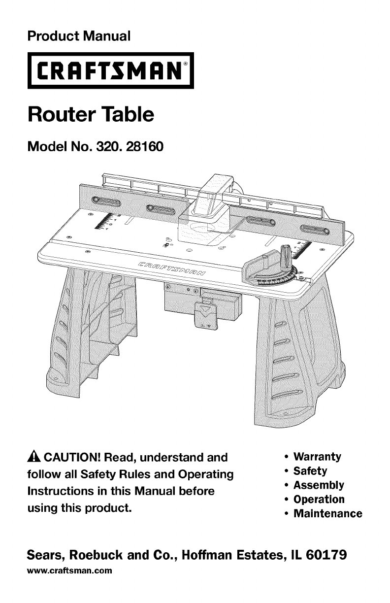
Product ManualI CRRFTSMRN+IRouter TableModel No. 320. 28160CAUTION! Read, understand andfollow all Safety Rules and OperatingInstructions in this Manu
Do not plug the router power cord into a wall outlet. It must be pluggedinto the router table switch. Power tool switches and controls need to bewithi
I'4_[1_71 [[l]l_ _llll i _ II q:1:] I =Your router table has a precision-built electric switch box and it should be con-nected to only a 120-volt
8. Fastening holes (11/32-inch dia.) allow the Router Table to be fixed to astable work surface.9. Integrated switch shield prevents dust from accumul
Key NO. Description Quantity1 Router table surface assembly 12 Table leg 23 Fence assembly 14 Miter-gauge assembly 15 Clamping knob 36 Short, round-he
ATTACHING THE LEGS TO THE TABLETOP1.2.3.4.Place the router tablesurface upside down ona flat, level surface, withthe underside of the tablefacing up.P
ATTACHING THE ROUTERTO THE TABLEAttach the router to the routertable after you have assem-bled the table.1. Place the router tableupright, with the fr
ATTACHING THE FENCE TOTHE TABLE (Fig. 6)_, WARNING: Alwaysunplug the router before at-taching or removing the fence.The fence has been shippedcomplete
4. Drill a hole at each of the marked locations.5. Place the router table on the work surface, and align the holes in the tablelegs with the holes in
3. To turn the router OFF,push the ON/OFF switchdown. (Fig. 11)AWARNING: Never leavethe router unattended while itis running or before it comesto a co
ADJUSTING THE FENCEThe fence enables you to sup-port and guide the work piece.To adjust the extended fenceforward and backward (Fig. 13)1. Loosen the
Warranty Page 2Safety Symbols Pages 3-4Safety Instructions Pages 5-10Know Your Router Table Pages 11-12Unpacking and Checking Contents Page 12Parts li
ADJUSTING THE MITER GAUGE (Fig. 16)1.2.3.Loosen the miter gauge knob.Rotate the miter gauge to the desired angle.Tighten the miter Fig. 16gauge knob.A
USING THE ROUTER WITH THE ROUTER TABLE1. Read the and understand entire Product Manual for the router.2. Always plug the router into the switched outl
GENERAL MAINTENANCE,_ WARNING: Avoid using solvents when cleaning plastic parts. Most plasticsare susceptible to damage from various types of commerci
Router Table MODEL NUMBER 320.28160Always mention the Model Number when ordering parts for this tool.® ®ff\ \28160 Manual_Revised_07-0228 Page 23
Router Table MODEL NUMBER 320.28160Always mention the Model Number when ordering parts for this tool.1 3402187000 Fence Knob2 5650017000 Plain Washer3
28160Manual_Revised_07-0228 Page25
I _[O_hlj_',.,.'_28160 Manual_Revised_07-0228 Page 26
28160Manual_Revised_07-0228 Page27
Your HomeFor expert troubleshooting and home solutions advice:manage homewww.managemyhome.comFor repair - in your home - of all major brand appliances
The purpose of safety symbols is to attract your attention to possible dangers. Thesafety symbols, and the explanations with them, deserve your carefu
Some of these following symbols may be used on this tool. Please study them andlearn their meaning. Proper interpretation of these symbols will allow
_._.'_iI _lIi_dll __._ilii_liI_]iliEo_._].AWARNING: READ AND UNDERSTAND ALL INSTRUCTIONS. Failure to fol-low all instructions listed below and th
• Use only 3-wire extension cords that have 3-prong grounding plugs and 3-pole receptacles that accept the tool's plug.• Repair or replace a dama
Table A shows the correct size to use, depending on cord length and ampererating. If in doubt, use the next heavier gauge: the smaller the gauge numbe
_, WARNING: The operation of any power tool can result in foreign objects be-ing thrown into your eyes, which can result in severe eye damage. Before
Do not force the tool. Use the correct tool and blade for your application.The correct tool and cutter will do the job better and more safely at the r
More documents for Power tools Craftsman 320.28160

Related products and manuals for Power tools Craftsman 320.28160
 (40 pages)
 (24 pages)
© 2020, manymanuals.com. All rights reserved. | 0.446 s |
 Manymanuals.com
 Manymanuals.de
 Manymanuals.fr
 Manymanuals.it
 Manymanuals.pl
 Manymanuals.cz
 Manymanuals.es
 Manymanuals-pt.com
Comments to this Manuals